
Flex Circuits
A flex circuit is a printed circuit board designed for flexible and dynamic applications. These types of PCBs use a thin substrate made of polyimide or polyester film that is etched with conductor traces and then covered with a protective layer of coverlay material. The end result is a very thin, lightweight PCB that can be bent or flexed without breaking. When designing a flex circuit, it is important to consider several key thermal considerations.
The first consideration is the base material. The base material provides the primary physical and electrical characteristics of the flex circuit. Most flex circuits utilize a polyimide (PI) film as the base because it is very flexible and retains flexibility after being thermoset. The PI also has superior resistance to humidity and tears than many other thermosetting materials.
Once the PI is in place, the design of the conductive pattern and copper traces must be considered. The traces must be spaced correctly to allow for adequate heat dissipation. This will also impact the maximum operating temperature of the flex circuit.
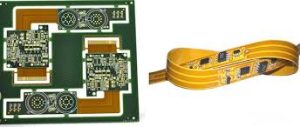
Thermal Considerations for Flex Circuits
While a wide range of etch patterns can be used with flex circuits, it is generally best to avoid overlapping traces and to stagger traces in adjacent layers. This will reduce stress on the flex substrate and increase the longevity of the copper trace. It is also important to make sure that all signal traces are routed on both sides of the flex circuit. This will ensure that the traces are not in contact with each other when the board is bent or flexed during use.
Another crucial aspect of a flex circuit is the thickness of the copper. Thicker copper is more durable and able to withstand higher operating temperatures, but it will also increase the cost of production. It is necessary to determine the maximum operating temperature requirements of the flex circuit before selecting a thickness.
Depending on the application, the flex circuit may require additional features such as stiffeners to support component or connector areas, PSAs (pressure-sensitive adhesive) to attach the flex to its enclosure, or shielding films for EMI sensitive applications. All of these additional components can increase the cost of the flex circuit.
Finally, it is important to consider whether the flex circuit will be fabricated using panel plating or pad-only plating (button plating). Button plating is a more expensive process that allows the manufacture to control the amount of copper deposited on the pads and increases etch yields in small traces. Panel plating, on the other hand, is more economical as the copper is deposited onto the entire surface of the circuit board.
The key considerations when designing a flex circuit are the thickness of the copper, the spacing between the traces, and the maximum operating temperature. Keeping these in mind will help you select the right construction for your project and provide a high-quality, long-lasting product. PCBWay can do some electrical testing on your flex circuit to ensure everything went well during manufacturing, but it will be an additional cost.

