
electrical testing procedures for electronics circuit boards
If you need to test the performance and functionality of a circuit board, you can perform a variety of electrical testing procedures. These tests are designed to help you find and repair any issues that may affect the board’s performance or reliability. These tests include visual inspections, power and ground connection testing, component functionality tests, and input/output tests.
Before performing any of these tests, you should review the board’s schematic diagram to ensure that you have a full understanding of its design and functionality. This can also help you narrow down the possible causes of any issues that arise during testing. In addition, it’s important to take steps to prepare the board for testing by ensuring that all components are clean and dry. You should also wear an anti-static wrist strap to avoid transferring any static charge to the board or its components.
Start by conducting a visual inspection of the electronics circuit boards to identify any physical damage or defects that could impact its performance. Then, conduct a continuity test using a multimeter or dedicated continuity tester to verify that all signal paths and traces are connected. If you detect a break in continuity, use a cross-probing tool to match up the location of a trace on the schematic diagram with its physical location on the circuit board.
What are the electrical testing procedures for electronics circuit boards?
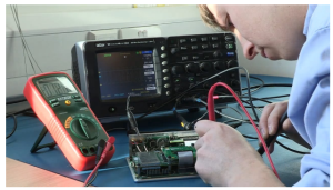
Next, conduct functional testing by applying input signals to the circuit board and analyzing the output signals. This process can help you pinpoint any issues with the board’s connectivity, power distribution, and timing. Input/output tests are often conducted using a signal generator to apply input signals and a multimeter or oscilloscope to measure the output signals.
After conducting the functional tests, you can conduct other specific circuit board testing techniques to evaluate the quality and performance of the finished product. These tests can include a DC sweep analysis and a transient analysis. These analyses examine the DC transfer curve and determine whether the circuit board works properly within its limits. They can also be used to assess the circuit board’s ability to handle varying input conditions, such as a peak load or sudden change in voltage.
In addition, you can also conduct capacitance testing and resistance testing to identify any shorts or other problems. For example, you can measure the resistance of a resistor by connecting the leads to the two terminals and using a digital multimeter set to the ohms (O) setting. You can also measure the capacitance of a capacitor by connecting the leads to the capacitor’s terminals and observing the resulting reading on a capacitance meter.


